What Instrument Is Used to Measure Wind Speed

An anemometer is a device used for measuring wind speed and management. It is also a mutual weather station instrument. The term is derived from the Greek word anemos, which means current of air, and is used to depict whatever wind speed instrument used in meteorology. The beginning known clarification of an anemometer was given by Leon Battista Alberti in 1450.
History
The anemometer has changed lilliputian since its development in the 15th century. Leon Battista Alberti (1404–1472) is said to have invented the first mechanical anemometer around 1450. In the ensuing centuries numerous others, including Robert Hooke (1635–1703), developed their ain versions, with some existence mistakenly credited every bit the inventor. In 1846, John Thomas Romney Robinson (1792–1882) improved upon the design by using four hemispherical cups and mechanical wheels. In 1926, Canadian meteorologist John Patterson (Jan 3, 1872 – February 22, 1956) developed a three-cup anemometer, which was improved by Brevoort and Joiner in 1935. In 1991, Derek Weston added the ability to mensurate air current management. In 1994, Andreas Pflitsch developed the sonic anemometer.[1]
Velocity anemometers
Loving cup anemometers
A simple type of anemometer was invented in 1845 by Rev Dr John Thomas Romney Robinson, of Armagh Observatory. Information technology consisted of iv hemispherical cups mounted on horizontal arms, which were mounted on a vertical shaft. The air flow past the cups in any horizontal direction turned the shaft at a rate that was roughly proportional to the air current speed. Therefore, counting the turns of the shaft over a set time interval produced a value proportional to the boilerplate wind speed for a wide range of speeds. It is also called a rotational anemometer.
On an anemometer with four cups, it is like shooting fish in a barrel to run into that since the cups are bundled symmetrically on the finish of the arms, the wind always has the hollow of one cup presented to it and is blowing on the back of the loving cup on the opposite end of the cross. Since a hollow hemisphere has a drag coefficient of .38 on the spherical side and 1.42 on the hollow side,[2] more force is generated on the cup that is presenting its hollow side to the wind. Because of this asymmetrical force, torque is generated on the centrality of the anemometer, causing it to spin.
Theoretically, the speed of rotation of the anemometer should exist proportional to the wind speed because the forcefulness produced on an object is proportional to the speed of the fluid flowing past information technology. However, in practice other factors influence the rotational speed, including turbulence produced by the apparatus, increasing drag in opposition to the torque that is produced by the cups and support artillery, and friction of the mount point. When Robinson get-go designed his anemometer, he asserted that the cups moved 1-third of the speed of the current of air, unaffected by the cup size or arm length. This was apparently confirmed by some early on independent experiments, only it was wrong. Instead, the ratio of the speed of the air current and that of the cups, the anemometer factor, depends on the dimensions of the cups and arms, and may have a value betwixt 2 and a niggling over three. Every previous experiment involving an anemometer had to be repeated subsequently the error was discovered.
The three-cup anemometer adult by the Canadian John Patterson in 1926 and subsequent cup improvements by Brevoort & Joiner of the U.s. in 1935 led to a cupwheel design with a nearly linear response and had an error of less than iii% up to threescore mph (97 km/h). Patterson establish that each cup produced maximum torque when it was at 45° to the wind flow. The three-loving cup anemometer also had a more constant torque and responded more quickly to gusts than the 4-cup anemometer.
The three-cup anemometer was farther modified by the Australian Dr. Derek Weston in 1991 to mensurate both wind direction and wind speed. Weston added a tag to one loving cup, which causes the cupwheel speed to increase and subtract equally the tag moves alternately with and against the wind. Wind direction is calculated from these cyclical changes in cupwheel speed, while wind speed is adamant from the average cupwheel speed.
Three-cup anemometers are currently used as the industry standard for wind resources assessment studies & practice.
Vane anemometers
Ane of the other forms of mechanical velocity anemometer is the vane anemometer. It may be described equally a windmill or a propeller anemometer. Unlike the Robinson anemometer, whose centrality of rotation is vertical, the vane anemometer must have its centrality parallel to the direction of the wind and is therefore horizontal. Furthermore, since the air current varies in direction and the axis has to follow its changes, a current of air vane or some other contrivance to fulfill the same purpose must exist employed.
A vane anemometer thus combines a propeller and a tail on the aforementioned axis to obtain accurate and precise wind speed and direction measurements from the same instrument.[iii] The speed of the fan is measured by a rev counter and converted to a windspeed past an electronic chip. Hence, volumetric flow rate may be calculated if the cross-sectional area is known.
In cases where the direction of the air motion is always the same, as in ventilating shafts of mines and buildings, wind vanes known as air meters are employed, and give satisfactory results.[4]
- Vane anemometers
-

Vane style of anemometer
-
Manus-held depression-speed vane anemometer
-

Paw-held digital anemometer or Byram anenometer.
Hot-wire anemometers

Hot wire anemometers employ a fine wire (on the lodge of several micrometres) electrically heated to some temperature in a higher place the ambient. Air flowing past the wire cools the wire. Every bit the electrical resistance of most metals is dependent upon the temperature of the metallic (tungsten is a pop option for hot-wires), a relationship tin be obtained between the resistance of the wire and the speed of the air.[five] In near cases, they cannot be used to measure the direction of the airflow, unless coupled with a wind vane.
Several ways of implementing this exist, and hot-wire devices can be further classified as CCA (abiding current anemometer), CVA (constant voltage anemometer) and CTA (abiding-temperature anemometer). The voltage output from these anemometers is thus the issue of some sort of circuit within the device trying to maintain the specific variable (current, voltage or temperature) constant, following Ohm's law.
Additionally, PWM (pulse-width modulation) anemometers are too used, wherein the velocity is inferred past the time length of a repeating pulse of current that brings the wire up to a specified resistance so stops until a threshold "floor" is reached, at which time the pulse is sent once more.
Hot-wire anemometers, while extremely delicate, take extremely high frequency-response and fine spatial resolution compared to other measurement methods, and equally such are virtually universally employed for the detailed study of turbulent flows, or any flow in which rapid velocity fluctuations are of involvement.
An industrial version of the fine-wire anemometer is the thermal flow meter, which follows the same concept, merely uses two pins or strings to monitor the variation in temperature. The strings comprise fine wires, but encasing the wires makes them much more durable and capable of accurately measuring air, gas, and emissions flow in pipes, ducts, and stacks. Industrial applications often incorporate dirt that will damage the archetype hot-wire anemometer.

Drawing of a laser anemometer. The laser low-cal is emitted (ane) through the front lens (half dozen) of the anemometer and is backscattered off the air molecules (7). The backscattered radiation (dots) re-enters the device and is reflected and directed into a detector (12).
Laser Doppler anemometers
In laser Doppler velocimetry, laser Doppler anemometers use a beam of low-cal from a laser that is divided into two beams, with i propagated out of the anemometer. Particulates (or deliberately introduced seed cloth) flowing along with air molecules about where the axle exits reflect, or backscatter, the calorie-free back into a detector, where it is measured relative to the original laser beam. When the particles are in great motion, they produce a Doppler shift for measuring air current speed in the light amplification by stimulated emission of radiation light, which is used to summate the speed of the particles, and therefore the air around the anemometer.[6]

2d ultrasonic anemometer with 3 paths
Ultrasonic anemometers
Ultrasonic anemometers, first developed in the 1950s, employ ultrasonic sound waves to measure wind velocity. They measure wind speed based on the time of flight of sonic pulses between pairs of transducers. Measurements from pairs of transducers can be combined to yield a measurement of velocity in i-, two-, or three-dimensional flow. The spatial resolution is given by the path length between transducers, which is typically 10 to 20 cm. Ultrasonic anemometers can take measurements with very fine temporal resolution, 20 Hz or better, which makes them well suited for turbulence measurements. The lack of moving parts makes them advisable for long-term use in exposed automated weather stations and weather buoys where the accuracy and reliability of traditional cup-and-vane anemometers are adversely afflicted by salty air or dust. Their primary disadvantage is the baloney of the air menstruum by the construction supporting the transducers, which requires a correction based upon wind tunnel measurements to minimize the effect. An international standard for this process, ISO 16622 Meteorology—Ultrasonic anemometers/thermometers—Acceptance exam methods for mean air current measurements is in general circulation. Some other disadvantage is lower accuracy due to atmospheric precipitation, where rain drops may vary the speed of sound.
Since the speed of audio varies with temperature, and is virtually stable with pressure change, ultrasonic anemometers are likewise used every bit thermometers.
Two-dimensional (air current speed and wind direction) sonic anemometers are used in applications such as weather stations, ship navigation, aviation, weather buoys and wind turbines. Monitoring current of air turbines unremarkably requires a refresh rate of wind speed measurements of 3 Hz,[7] easily achieved by sonic anemometers. Iii-dimensional sonic anemometers are widely used to mensurate gas emissions and ecosystem fluxes using the boil covariance method when used with fast-response infrared gas analyzers or laser-based analyzers.
Two-dimensional wind sensors are of 2 types:
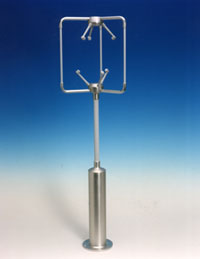
- Two ultrasounds paths: These sensors have four arms. The disadvantage of this type of sensor is that when the wind comes in the direction of an ultrasound path, the artillery disturb the airflow, reducing the accuracy of the resulting measurement.
- Three ultrasounds paths: These sensors have iii arms. They give one path redundancy of the measurement which improves the sensor accuracy and reduces aerodynamic turbulence.
Audio-visual resonance anemometers
Acoustic resonance anemometer
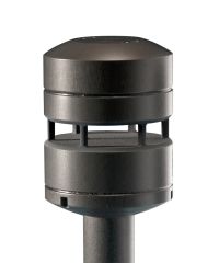
Acoustic resonance anemometers are a more contempo variant of sonic anemometer. The technology was invented by Savvas Kapartis and patented in 1999.[8] Whereas conventional sonic anemometers rely on time of flight measurement, audio-visual resonance sensors use resonating acoustic (ultrasonic) waves inside a small purpose-built cavity in society to perform their measurement.

Acoustic resonance principle
Congenital into the cavity is an array of ultrasonic transducers, which are used to create the separate standing-wave patterns at ultrasonic frequencies. As wind passes through the cavity, a modify in the wave's property occurs (phase shift). By measuring the amount of phase shift in the received signals by each transducer, and then past mathematically processing the data, the sensor is able to provide an accurate horizontal measurement of wind speed and management.
Because acoustic resonance engineering science enables measurement inside a modest cavity, the sensors tend to be typically smaller in size than other ultrasonic sensors. The minor size of acoustic resonance anemometers makes them physically strong and easy to rut, and therefore resistant to icing. This combination of features means that they achieve high levels of data availability and are well suited to wind turbine control and to other uses that require small robust sensors such as battlefield meteorology. One issue with this sensor type is measurement accuracy when compared to a calibrated mechanical sensor. For many end uses, this weakness is compensated for by the sensor's longevity and the fact that it does not require recalibration once installed.
Ping-pong ball anemometers
A common anemometer for basic employ is constructed from a ping-pong ball attached to a string. When the wind blows horizontally, it presses on and moves the brawl; because ping-pong balls are very lightweight, they move easily in light winds. Measuring the bending betwixt the string-ball apparatus and the vertical gives an guess of the wind speed.
This type of anemometer is mostly used for middle-school level instruction, which about students make on their own, but a similar device was likewise flown on the Phoenix Mars Lander.[nine]
Pressure level anemometers

The start designs of anemometers that mensurate the pressure were divided into plate and tube classes.
Plate anemometers
These are the get-go modern anemometers. They consist of a flat plate suspended from the pinnacle so that the wind deflects the plate. In 1450, the Italian art architect Leon Battista Alberti invented the get-go mechanical anemometer; in 1664 it was re-invented by Robert Hooke (who is often mistakenly considered the inventor of the first anemometer). Later versions of this class consisted of a flat plate, either foursquare or circular, which is kept normal to the wind by a wind vane. The pressure level of the wind on its face is balanced by a spring. The compression of the spring determines the actual force which the wind is exerting on the plate, and this is either read off on a suitable guess, or on a recorder. Instruments of this kind exercise non respond to light winds, are inaccurate for high wind readings, and are irksome at responding to variable winds. Plate anemometers have been used to trigger loftier wind alarms on bridges.
Tube anemometers

Tube anemometer invented past William Henry Dines. The movable role (right) is mounted on the fixed part (left).


The pointed head is the pitot port. The small holes are connected to the static port.
James Lind'south anemometer of 1775 consisted of a glass U tube containing a liquid manometer (pressure gauge), with one cease bent in a horizontal direction to face the wind and the other vertical end remains parallel to the wind menses. Though the Lind was not the kickoff it was the most practical and all-time known anemometer of this type. If the wind blows into the oral fissure of a tube it causes an increase of pressure on i side of the manometer. The wind over the open up cease of a vertical tube causes piddling change in pressure on the other side of the manometer. The resulting elevation difference in the two legs of the U tube is an indication of the current of air speed. Yet, an accurate measurement requires that the wind speed be directly into the open cease of the tube; modest departures from the true direction of the air current causes big variations in the reading.
The successful metal force per unit area tube anemometer of William Henry Dines in 1892 utilized the same force per unit area deviation between the open mouth of a straight tube facing the air current and a ring of small holes in a vertical tube which is closed at the upper end. Both are mounted at the same superlative. The pressure differences on which the activeness depends are very small, and special means are required to annals them. The recorder consists of a bladder in a sealed chamber partially filled with water. The pipe from the directly tube is continued to the top of the sealed chamber and the pipe from the small tubes is directed into the bottom within the float. Since the pressure difference determines the vertical position of the float this is a measure of the wind speed.[x]
The corking advantage of the tube anemometer lies in the fact that the exposed part can be mounted on a high pole, and requires no oiling or attending for years; and the registering part can be placed in any convenient position. Two connecting tubes are required. It might announced at first sight every bit though one connection would serve, but the differences in pressure on which these instruments depend are then minute, that the pressure of the air in the room where the recording part is placed has to be considered. Thus if the instrument depends on the pressure or suction outcome lonely, and this force per unit area or suction is measured against the air pressure in an ordinary room, in which the doors and windows are carefully closed and a newspaper is so burnt up the chimney, an event may be produced equal to a wind of 10 mi/h (16 km/h); and the opening of a window in crude weather, or the opening of a door, may entirely alter the registration.
While the Dines anemometer had an error of only i% at x mph (16 km/h), it did not reply very well to low winds due to the poor response of the apartment plate vane required to turn the caput into the wind. In 1918 an aerodynamic vane with viii times the torque of the flat plate overcame this problem.
Pitot tube static anemometers
Modernistic tube anemometers use the same principle as in the Dines anemometer just using a different blueprint. The implementation uses a pitot-static tube which is a pitot tube with two ports, pitot and static, that is normally used in measuring the airspeed of aircraft. The pitot port measures the dynamic pressure of the open oral fissure of a tube with pointed head facing air current, and the static port measures the static pressure from small holes along the side on that tube. The pitot tube is connected to a tail so that information technology always makes the tube'southward head to face the air current. Additionally, the tube is heated to foreclose rime ice formation on the tube.[eleven] There are ii lines from the tube down to the devices to measure the difference in pressure of the 2 lines. The measurement devices can exist manometers, pressure transducers, or analog chart recorders.[12]
Effect of density on measurements
In the tube anemometer the dynamic pressure is really existence measured, although the scale is ordinarily graduated as a velocity scale. If the actual air density differs from the scale value, due to differing temperature, peak or barometric pressure level, a correction is required to obtain the bodily wind speed. Approximately 1.5% (ane.vi% in a higher place 6,000 anxiety) should be added to the velocity recorded past a tube anemometer for each one thousand ft (5% for each kilometer) above sea-level.
Issue of icing
At airports, information technology is essential to accept accurate air current data under all conditions, including freezing precipitation. Anemometry is also required in monitoring and controlling the functioning of current of air turbines, which in common cold environments are prone to in-cloud icing. Icing alters the aerodynamics of an anemometer and may entirely block it from operating. Therefore, anemometers used in these applications must be internally heated.[xiii] Both cup anemometers and sonic anemometers are presently available with heated versions.
Musical instrument location
In order for wind speeds to be comparable from location to location, the effect of the terrain needs to be considered, especially in regard to elevation. Other considerations are the presence of trees, and both natural canyons and artificial canyons (urban buildings). The standard anemometer tiptop in open rural terrain is 10 meters.[14]
See also
- Air period meter
- Anemoi, for the ancient origin of the name of this technology
- Anemoscope, aboriginal device for measuring or predicting wind direction or weather
- Automatic aerodrome weather station
- Dark of the Big Current of air
- Particle image velocimetry
- Savonius wind turbine
- Wind ability forecasting
- Wind run
- Windsock, a simple loftier-visibility indicator of estimate wind speed and management
Notes
- ^ "History of the Anemometer". Logic Free energy. 2012-06-18.
- ^ Sighard Hoerner's Fluid Dynamic Drag, 1965, pp. 3–17, Effigy 32 (pg threescore of 455)
- ^ World Meteorological Arrangement. "Vane anemometer". Eumetcal. Archived from the original on 8 April 2014. Retrieved 6 April 2014.
- ^ Various (2018-01-01). Encyclopaedia Britannica, 11th Edition, Volume 2, Part i, Slice 1. Prabhat Prakashan.
- ^ "Hot-wire Anemometer explanation". eFunda. Archived from the original on x October 2006. Retrieved 18 September 2006.
- ^ Iten, Paul D. (29 June 1976). "Laser Doppler Anemometer". United states of america Patent and Trademark Office. Retrieved xviii September 2006.
- ^ Giebhardt, Jochen (December 20, 2010). "Chapter 11: Wind turbine status monitoring systems and techniques". In Dalsgaard Sørensen, John; N Sørensen, Jens (eds.). Wind Energy Systems: Optimising design and structure for safe and reliable operation. Elsevier. pp. 329–349. ISBN9780857090638.
- ^ Kapartis, Savvas (1999) "Anemometer employing standing wave normal to fluid flow and travelling wave normal to continuing moving ridge" U.Southward. Patent 5,877,416
- ^ "The Telltale project." Archived 20 Feb 2012 at the Wayback Car
- ^ Dines, W. H. (1892). "Anemometer Comparisons". Quarterly Periodical of the Royal Meteorological Society. 18 (83): 168. Bibcode:1892QJRMS..18..165D. doi:10.1002/qj.4970188303. Retrieved 14 July 2014.
- ^ "Instrumentation: Pitot Tube Static Anemometer, Part 1". Mt. Washington Observatory. Archived from the original on 14 July 2014. Retrieved fourteen July 2014.
- ^ "Instrumentation: Pitot Tube Static Anemometer, Function two". Mt. Washington Observatory. Archived from the original on 14 July 2014. Retrieved 14 July 2014.
- ^ Makkonen, Lasse; Lehtonen, Pertti; Helle, Lauri (2001). "Anemometry in Icing Conditions". Journal of Atmospheric and Oceanic Technology. 18 (9): 1457. Bibcode:2001JAtOT..18.1457M. doi:10.1175/1520-0426(2001)018<1457:AIIC>2.0.CO;2.

- ^ Oke, Tim R. (2006). "3.5 Wind speed and direction" (PDF). Initial Guidance to Obtain Representative Meteorological Observations At Urban Sites. Instruments and Observing Methods. Vol. 81. World Meteorological Organization. pp. 19–26. Retrieved four February 2013.
References
- Meteorological Instruments, Due west.East. Knowles Middleton and Athelstan F. Spilhaus, 3rd Edition revised, Academy of Toronto Press, Toronto, 1953
- Invention of the Meteorological Instruments, W. E. Knowles Middleton, The Johns Hopkins Press, Baltimore, 1969
External links
| | Wikimedia Commons has media related to Anemometer. |
| | Look up anemometer in Wiktionary, the free lexicon. |
- . Encyclopædia Britannica. Vol. 2 (ninth ed.). 1878. pp. 24–26.
- Dines, William Henry (1911). . Encyclopædia Britannica. Vol. two (11th ed.). pp. 2–3.
- Description of the development and the construction of an ultrasonic anemometer
- Blitheness Showing Sonic Principle of Operation (Time of Flight Theory) – Gill Instruments
- Collection of historical anemometer
- Principle of Performance: Acoustic Resonance measurement – FT Technologies
- Thermopedia, "Anemometers (light amplification by stimulated emission of radiation doppler)"
- Thermopedia, "Anemometers (pulsed thermal)"
- Thermopedia, "Anemometers (vane)"
- The Rotorvane Anemometer. Measuring both air current speed and direction using a tagged three-cup sensor
rooseveltgoist1945.blogspot.com
Source: https://en.wikipedia.org/wiki/Anemometer
0 Response to "What Instrument Is Used to Measure Wind Speed"
Postar um comentário